Stories
Oak Bar Stools
Oak Bar Stools
September 2018
Oak Bar Stools
September 2018
This project all started in the Fall of 2006 with an idea of a Christmas gift for Matt's mother at her new house, a nice hardwood front door. Around this same time Matt was invited to her place for dinner with his brother and a few other friends. She has a counter height table and four chairs around it. A normal table height is 30 inches. Her new table top sits a few inches higher at 36 inches, the standard counter height.
The problem was that with only four chairs, the six people attending dinner became separated between the table and her bar. The bar stools were too tall for the table and a normal chair was far too low. "Boy, wouldn't it be nice if these bar stools would just lower a bit and fit at the table when you needed them?"
After searching for a short while Matt was unsatisfied with what he found available in adjusting bar stools. For a few hours he sketched and then began to prototype a few components. This began the adventure. This was at a time when everything was hand drawn, with no help from any type of CAD software.
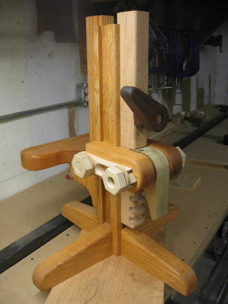
Out of the entire project, the largest challenge was locking the height of the stool safely. The three main parts that make up the stool are the Base, the Height Adjustment, and the Locking Device.
To see the full image gallery click here
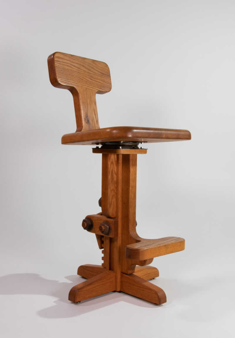
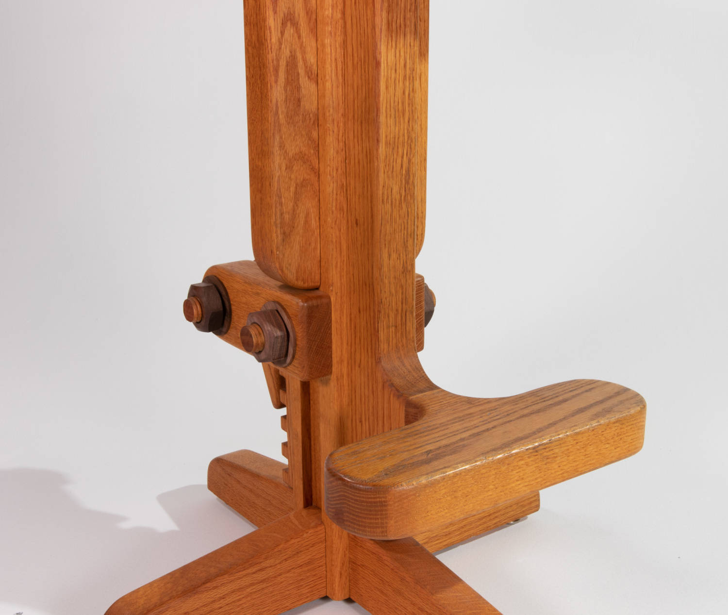
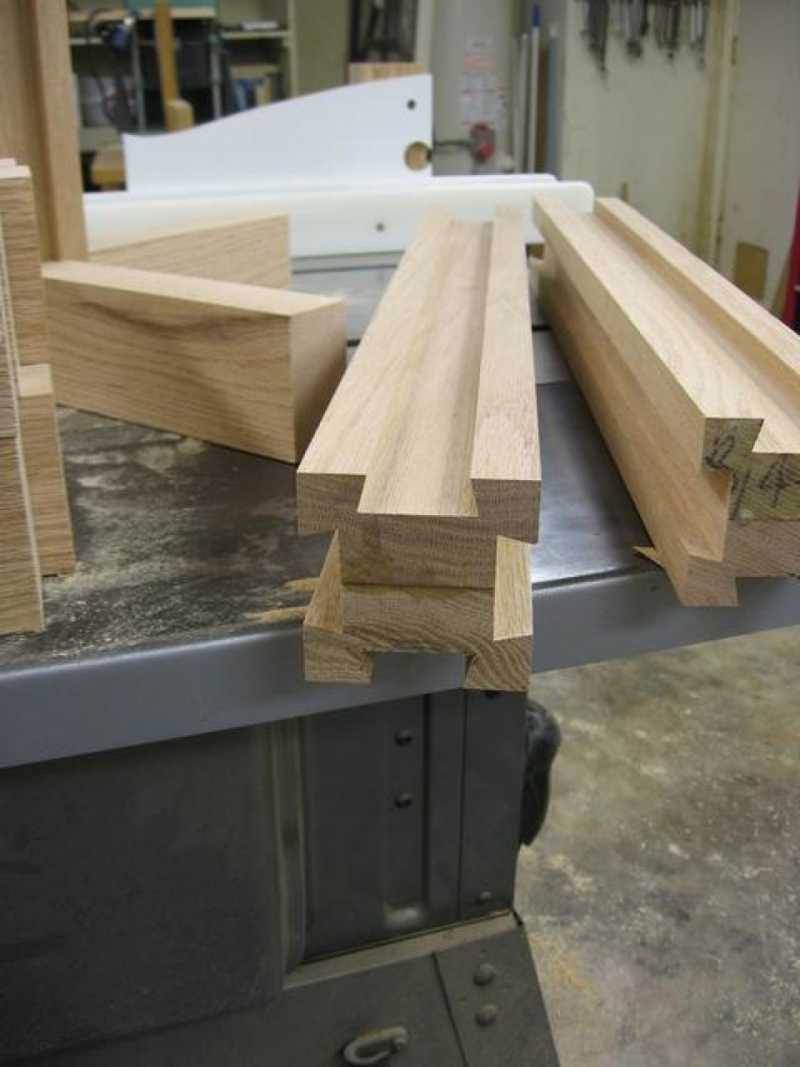
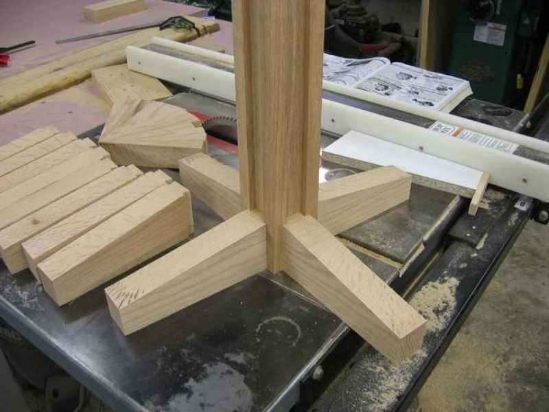
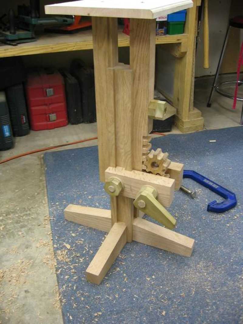
The Base
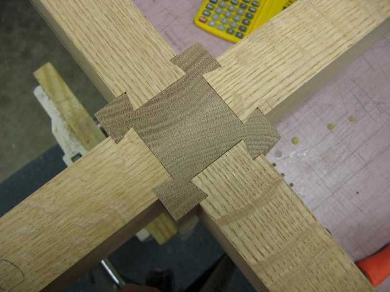
The base is made of solid oak that has a dovetail groove up each side of the column. I used this as the harness for each additional component. The feet are glued in place and later I add a steel support across the bottom.
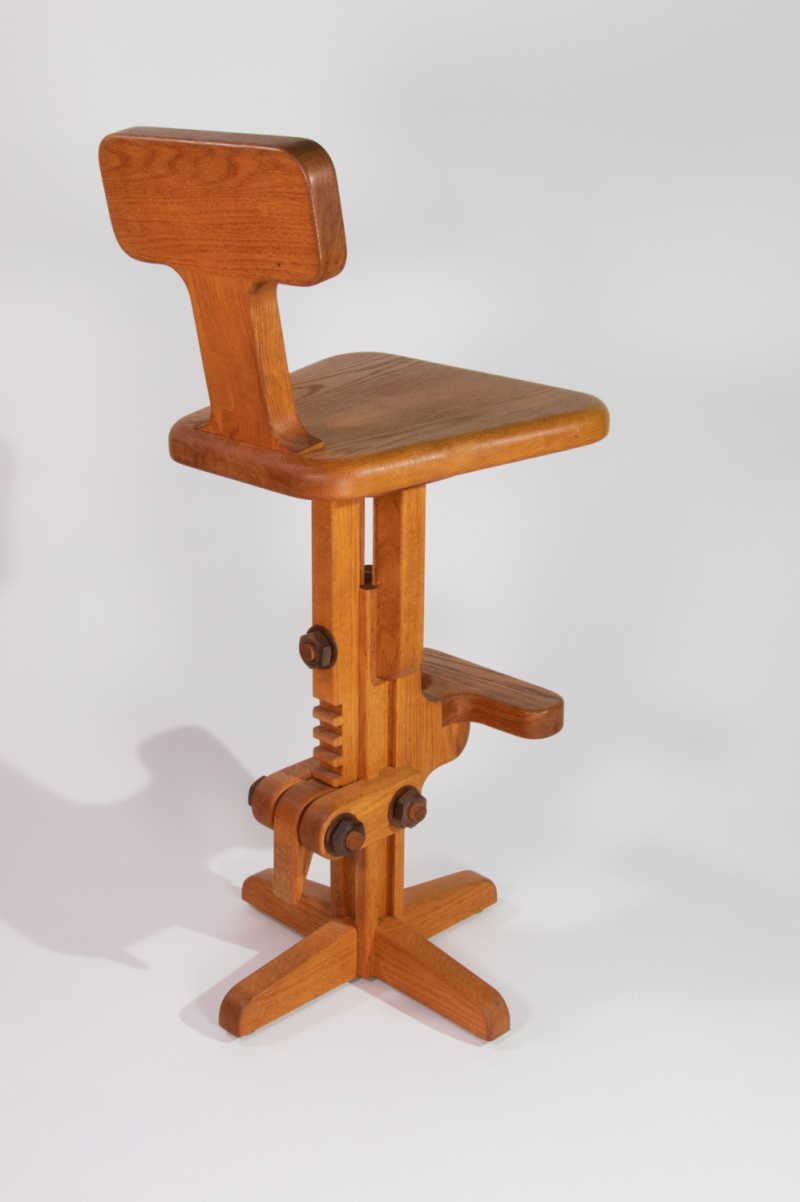
Height Adjustment
The ability to adjust the height of the stool from a bar height, to a counter height is the key to the whole design. I had recently made some jigs to sample some wooden gears. I started to experiment with a few different ways of using them to raise, lower, and lock the height of the stool seat.
Here you can see the first attempt at a rack and pinion setup. This was the original design to raise and lower the height but not to lock it.
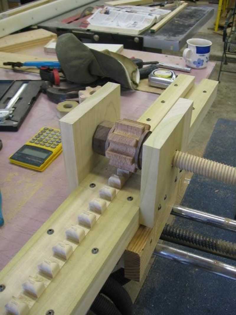
The first prototype completed using the rack and pinion proved quite nice at first. Later it was discovered that the overall weight of the stool became too much for this to work easily. In the end, adjusting the height is simply done by lifting on the seat back.
Locking Device
Attempt #1
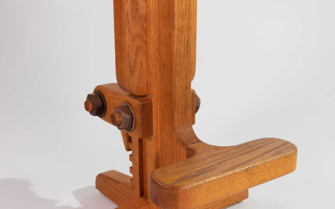
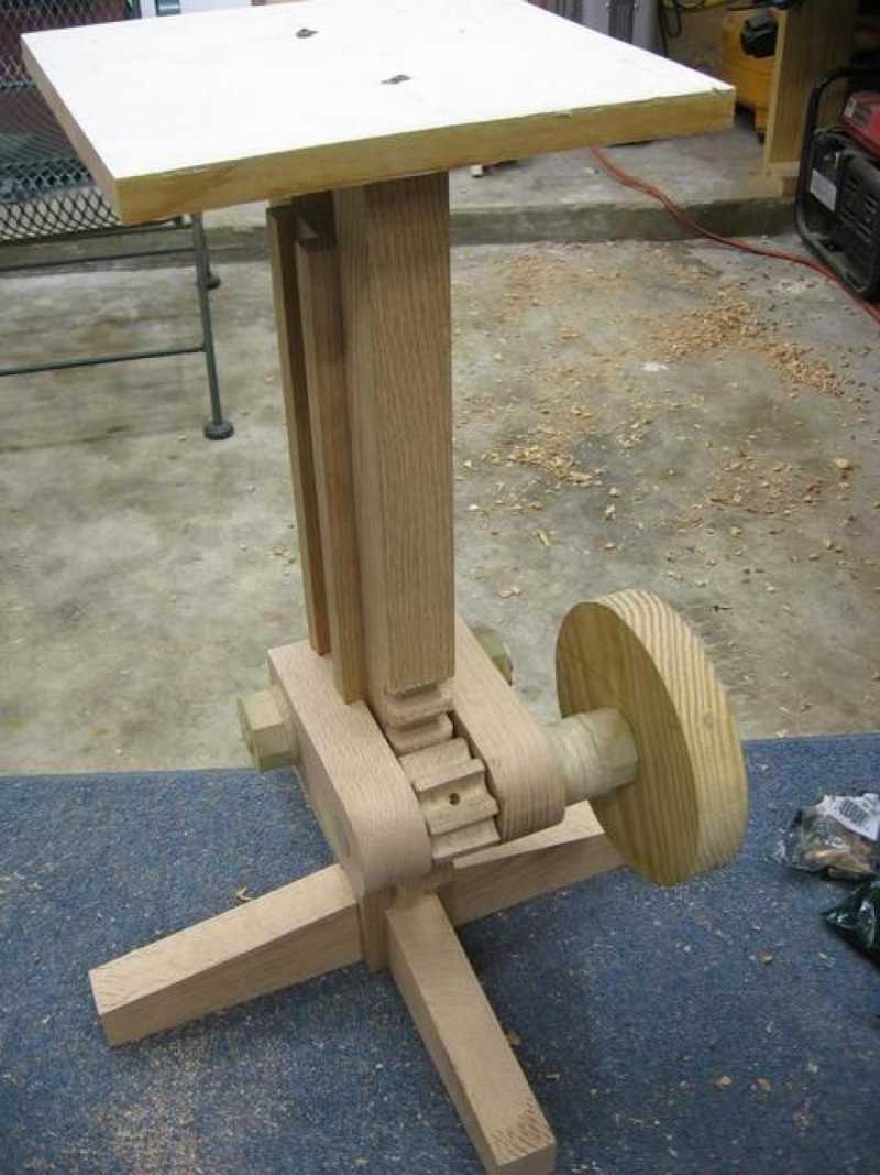
Locking the position proved a little more challenging than I had anticipated. The first attempt shown here was to run a threaded dowel from the front guide, through the center column, and out the back guide. There is a threaded handle that you can see on the end of the dowel against the back guide. Rotating the handle clockwise tightens the two guides against the column center. Although this is still used for stability, this would not work for the actual locking of the seat height.
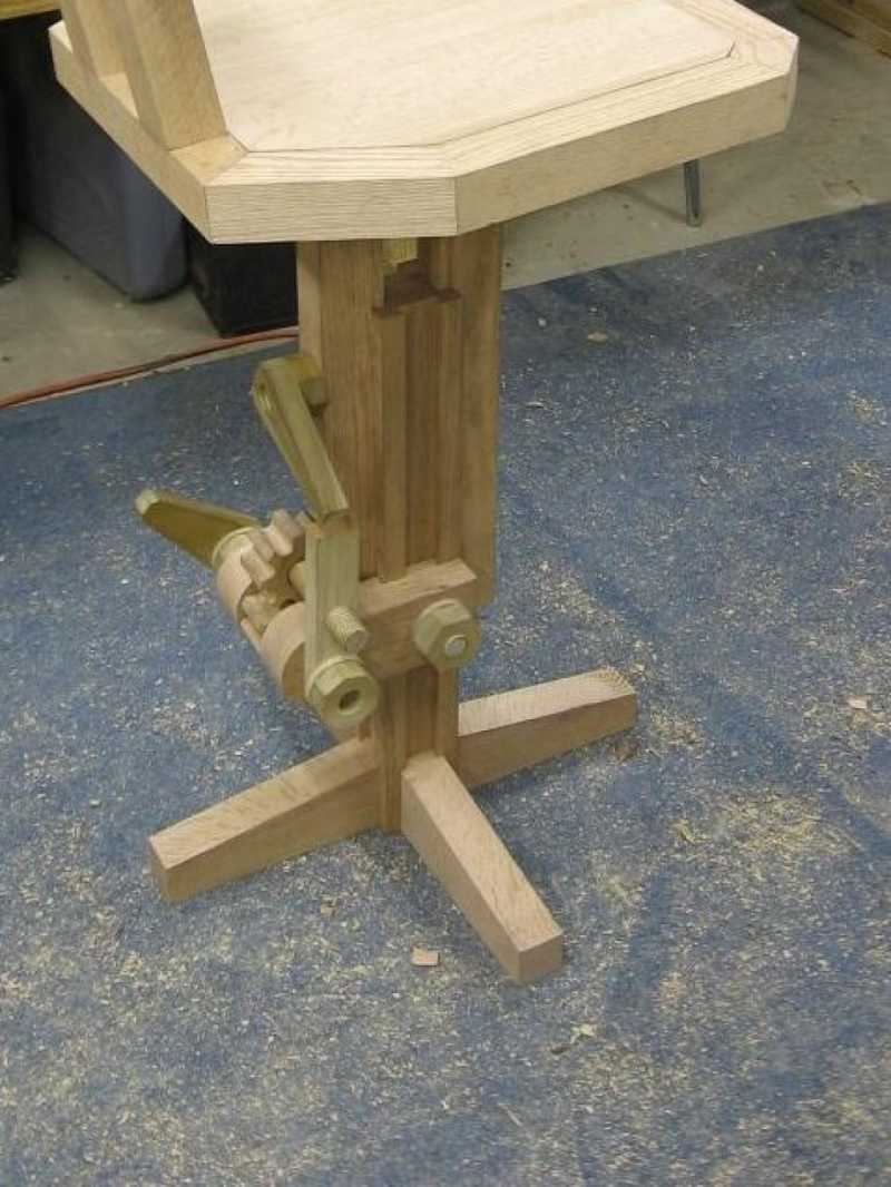
Attempt #2
This attempt did function, but I wasn't happy with it. It was a bit cumbersome to use and was questionable in terms of safety. In spite of all that, everyone did like the way it looked.
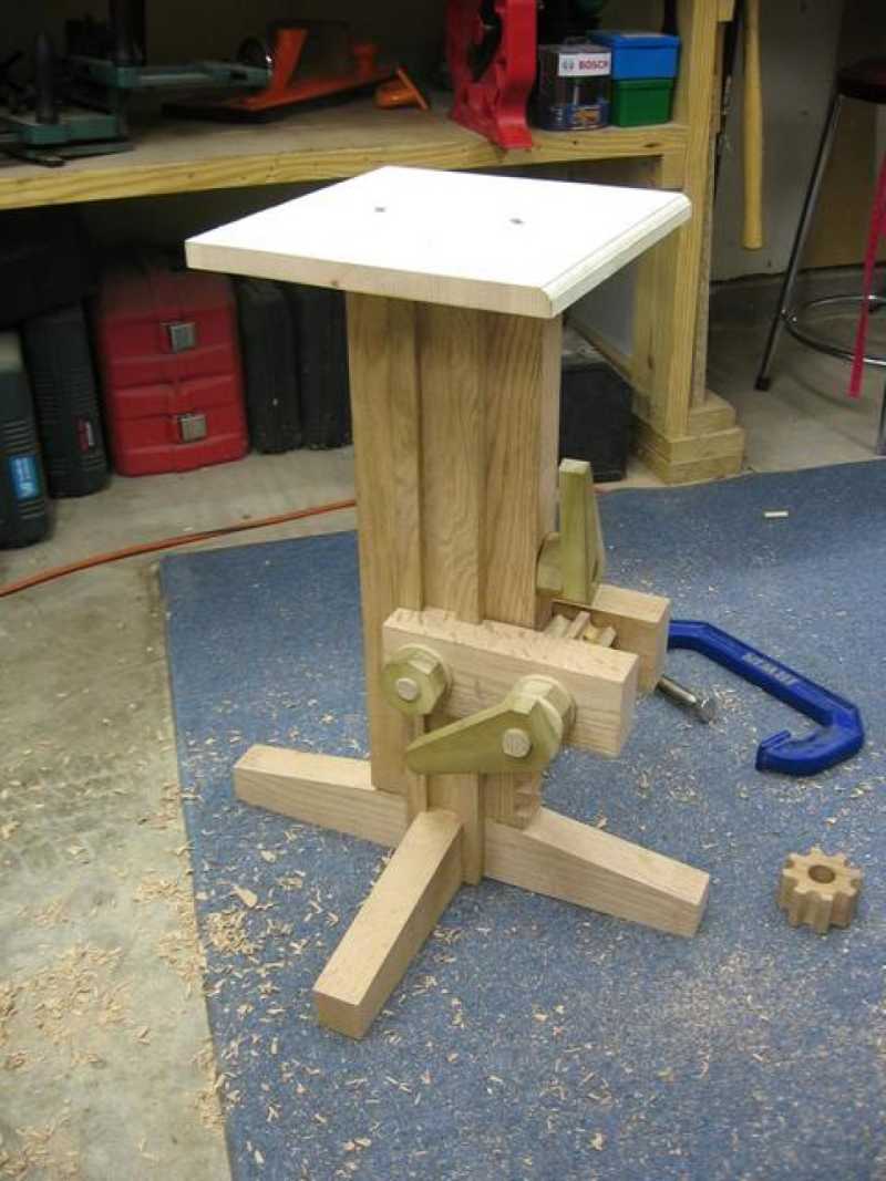
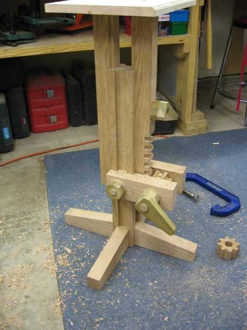
You can see by the first two images below that by throwing a second gear into the rack and pinion, the locking became stable enough to support the weight of an average human (200 lbs.)
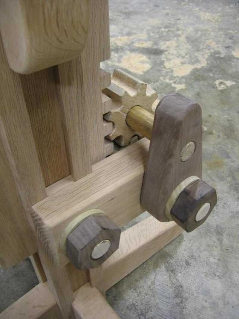
Attempt #3
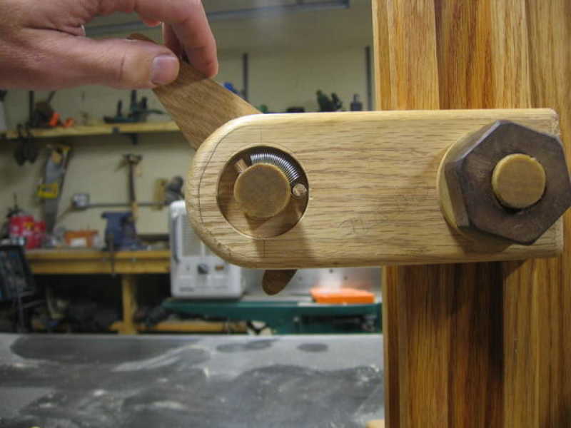
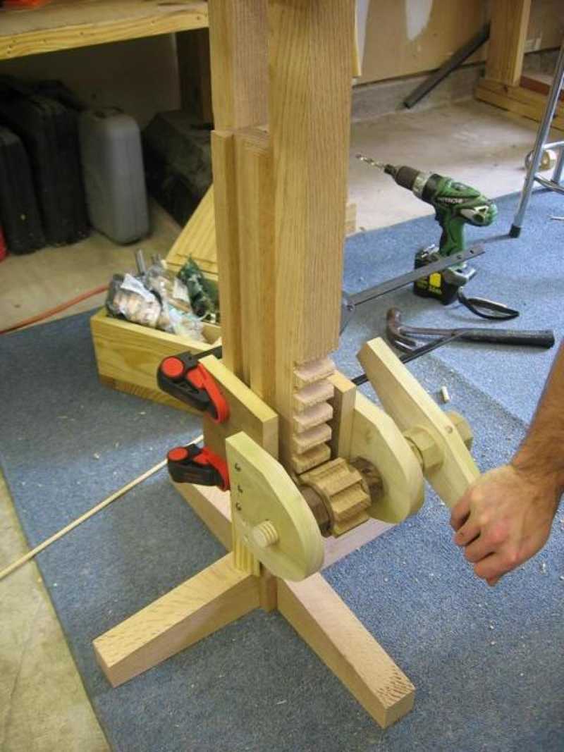
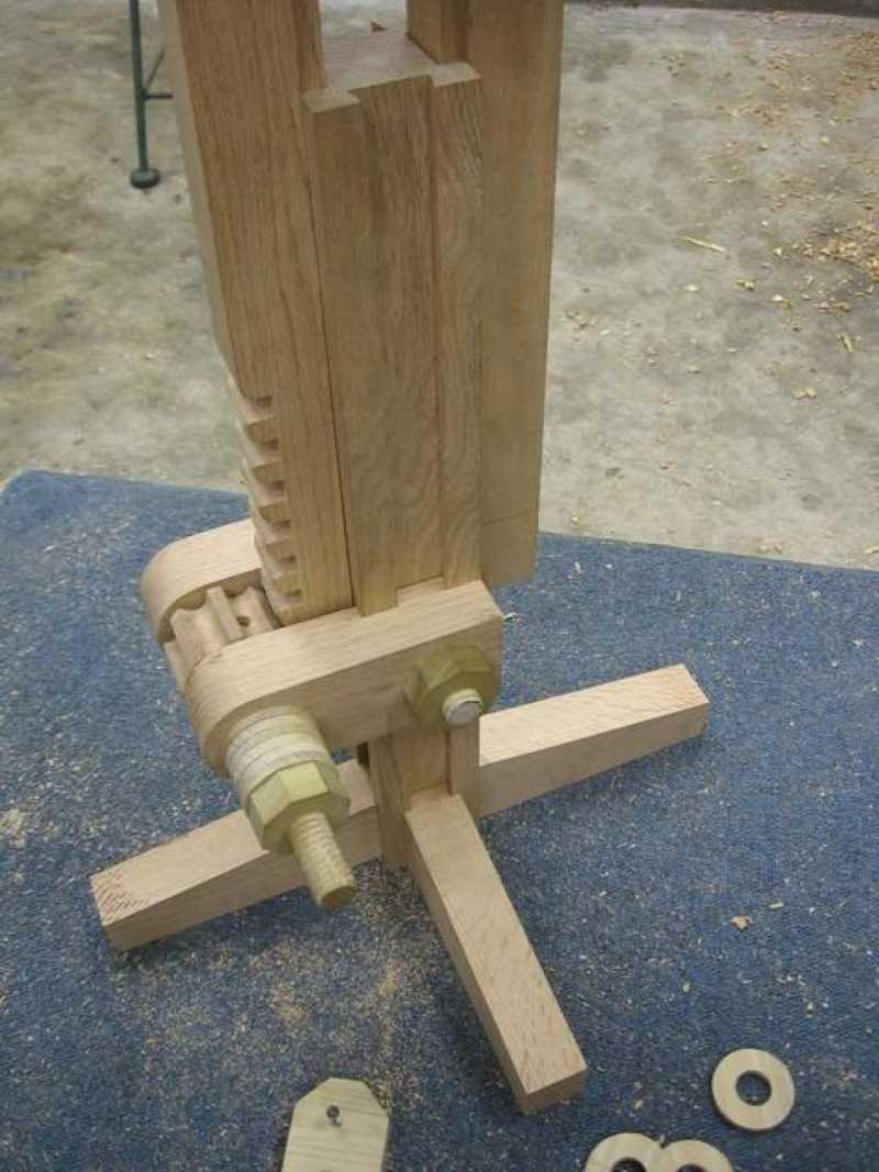
The third attempt at locking the height used two points of force. Below you can see how the locking tooth that replaced the gear keeps the rack from falling when it is rotated forward by resting the upper rack tooth against it's top. The second point of force comes from the rotation direction that is applied to the locking tooth. When the force is applied downward by the rack, the locking tooth then rotates inward, creating a binding pressure against the inner column.
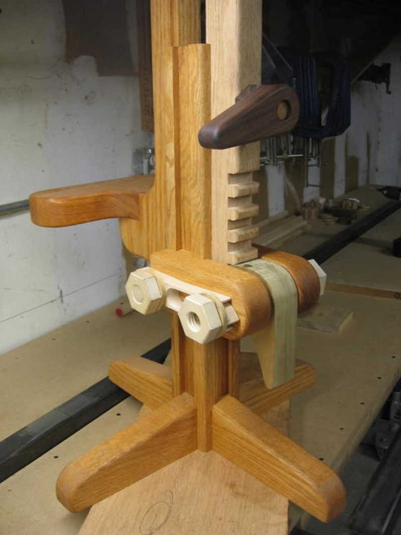
This solution was working well until I decided to give it a real test. I placed a temporary seat on top of the sliding guides and locked the height at the top. I sat down and started to move about, trying to simulate a normal social situation. After a few minutes I started increasing the amount of force by hopping up and down on the seat.
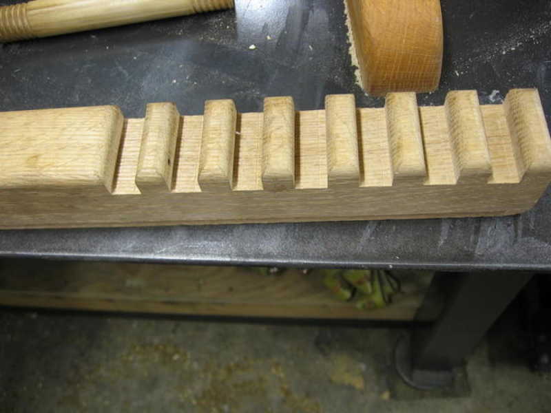
After 2-3 minutes, I finally broke the weight limit. The first rack tooth buckled which lead to then next three in line doing the same. In spite of the damage done, it was a very gentle descent. The damage only affected the rack itself, so I was pleased with the safety.
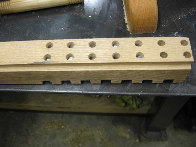
Attempt #4
Attempt #3 proved to work quite well with the exception of the rack strength. To solve this, I used a little help from my good friends at the local steel supplier. After carefully creating a jig to use on the drill press, I drilled two holes down the back side of rack and nearly all the way through each tooth and inserted steel dowels. I repeated the testing after this and found that I was unable to break them.
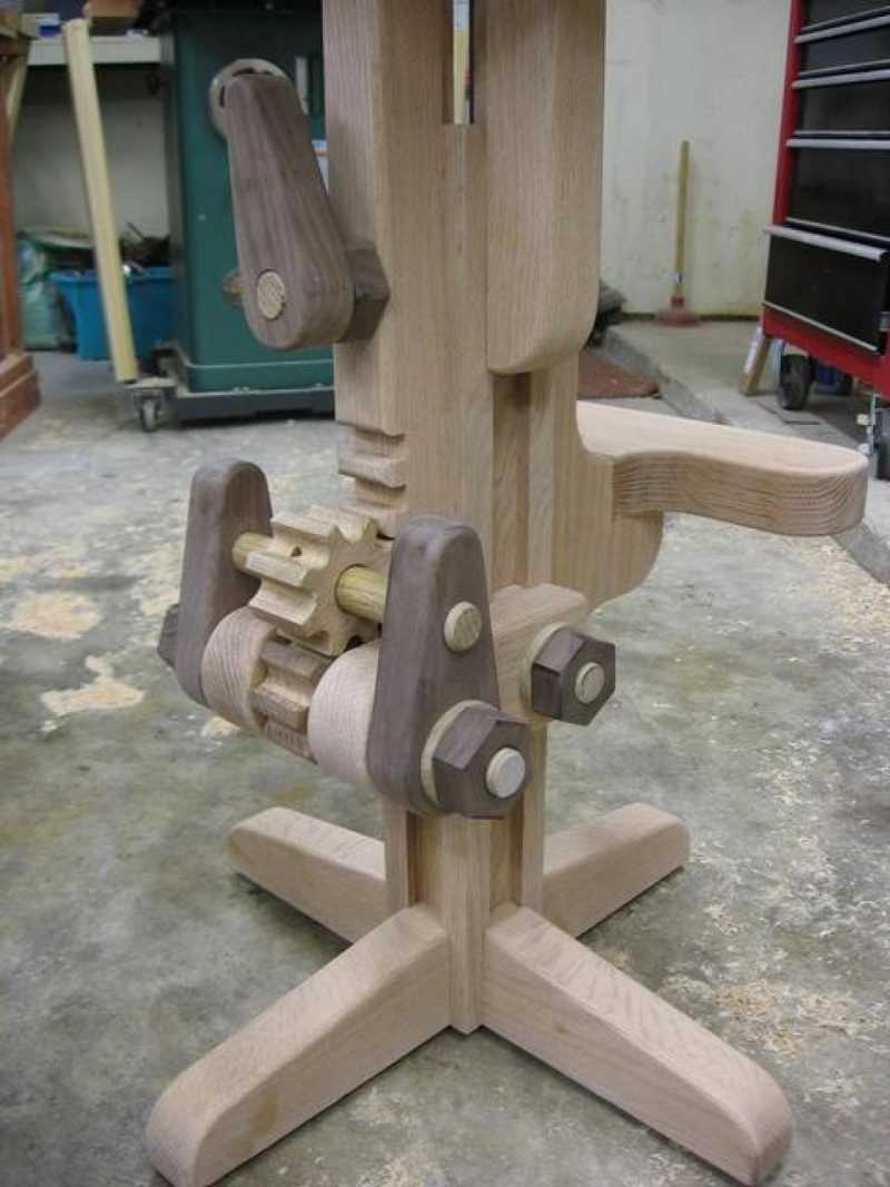
Attempt #5 - Final Locking Prototype
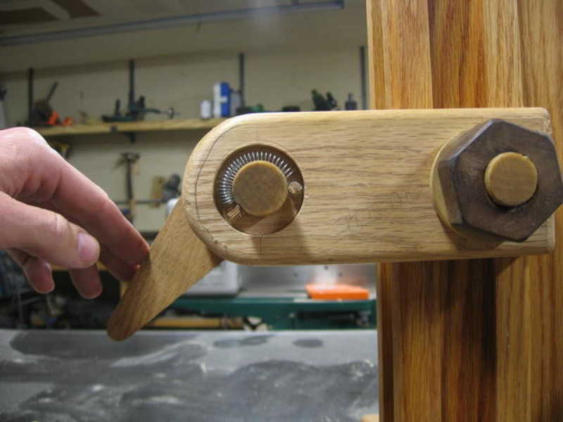
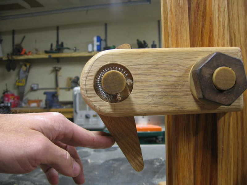
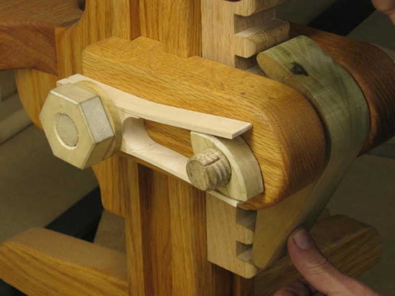
Now that the locking mechanism was functioning, I still had one problem left. The spring action to ensure that the locking tooth has a constant forward pressure was not going to last very long as I could see it already showing signs of stress from use.
The first attempt, as you can see in some of the previous photos, uses an American football shaped lobe that rotates between two pieces of hard maple. When rotated backwards ,the football shaped lobe spreads the maple fork creating pressure. When released, the maple fork closes down on the lob returning it to the locked position.